
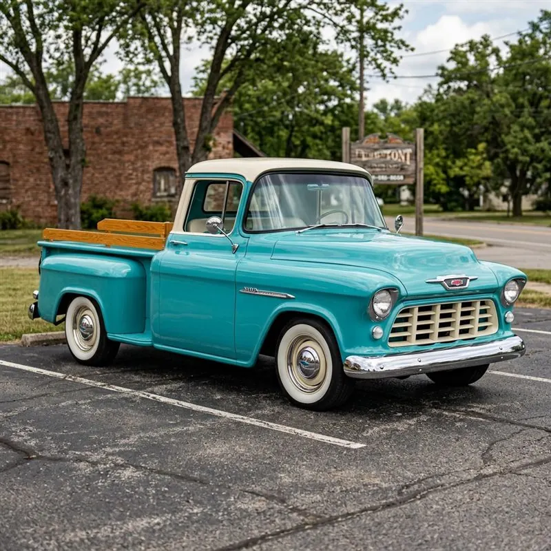
A digital dash installation transforms your classic car's cockpit with modern, reliable instrumentation. Nothing degrades the driving confidence of a classic car or street rod faster than unreliable, 50-year-old mechanical gauges. Bouncing speedometer needles, hot oil lines leaking under the dashboard carpet, uncalibrated mechanical temperature senders, and fuel gauges that float wildly around turns are common frustrations for classic vehicle owners.
Modern digital gauge clusters — engineered by industry leaders like Dakota Digital and Classic Instruments — eliminate these mechanical points of failure. Whether you are modernizing a 1955 Chevrolet 3100 pickup truck, a pro-touring 1969 Camaro SS build, or a custom street rod, retrofitting a digital instrument system delivers micro-processor accuracy, LED backlighting, customizable high-speed warnings, and seamless integration with GM LS3 or Ford Coyote engine swaps, or Holley EFI engine electronics. In this master guide, our electrical specialists at Carolina Street Rods walk you through every step of the installation process.
1. Choosing Your Instrument System: RTX vs VHX vs Classic Instruments
Before pulling out a single under-dash screw, selecting the proper gauge architecture for your interior build style is critical:
- Dakota Digital RTX Series (Factory Restomod Gold Standard): Designed to replicate OEM factory appearance when the vehicle ignition is off. When powered on, crisp LED illuminated needles sweep across CNC-machined bezels, accompanied by dual customizable TFT message centers displaying oil temp, transmission temp, gear position, 0-60 MPH timers, and system diagnostics. Bluetooth smartphone app configuration allows instant color tweaking.
- Dakota Digital VHX Series (Modern Backlit Performance): Features backlit analog needles, micro-stepper motors, and red/blue/white LED backlighting. A budget-friendly entry point for builders wanting solid-state reliability.
- Classic Instruments Bel Era / Velocity Series: Uses solid-state electric stepper motors housed inside traditional chrome bezel surrounds. Perfect for traditional 1930s street rods and Tri-Five Chevys wanting classic analog gauge styling without digital LCD screens.
2. Electrical Wiring Blueprint & Control Box Installation
Modern digital gauge systems decouple the gauge face from raw engine high-voltage signals using a central central processing control box (e.g., Dakota Digital HDX/RTX Control Box). Instead of running dozens of thick wires into the dash cluster, a single thin CAT-5 ethernet data cable connects the under-dash control module to the display assembly.
Primary Wiring Color Code & Pinout Reference Table:
| Terminal Name | Standard Wire Color | Power / Signal Source | Fuse Rating / Requirement |
|---|---|---|---|
| +12V IGN (Switched) | Pink / Red | Ignition Switch (Hot in Start & Run) | 5A In-Line Fuse |
| +12V BAT (Constant) | Orange / Yellow | Unswitched Battery Terminal (Clock memory) | 5A In-Line Fuse |
| GND (Ground) | Black | Chassis Ground Stud / Cylinder Head Strap | Clean Star-Washer Ring Terminal |
| DIM (Night Dimmer) | Green / Wire | Headlight Switch Park/Tail circuit | Triggers night brightness dimming |
| SPD (Speed Signal) | Purple / White | VSS Pulse Generator or ECU Speed Output | High/Low AC or 5V/12V square wave |
| TAC (Tachometer) | White | Coil (-) or ECU Tach Signal output | Set cylinder count (4, 6, 8 cyl) |
| FUEL (Fuel Level) | Tan / Blue | Tank Fuel Sender Signal Wire | Select Ohm curve (0-90 GM, 73-10 Ford) |
⚡ Electrical Master Rule: Star Grounding
Never ground the digital gauge control box to sheet metal under the dashboard using self-tapping screws. Paint rust and loose body panels cause voltage drops that distort fuel and oil pressure readings. Run a dedicated 14-AWG ground wire directly to a clean chassis ground stud or engine cylinder head ring terminal.
3. Sensor Plumbing & Metric Thread Adapters
Installing solid-state electronic senders into modern LS, LT, or Coyote engine blocks requires matching thread adapters:
Water Temperature Sender Installation:
GM LS cylinder heads feature metric M12x1.5 female threads located on the front driver-side head and rear passenger-side head. Install the digital water temperature sender into the rear passenger cylinder head using a brass M12x1.5 male to 1/8-inch NPT female adapter. Teflon tape should only be used on the NPT threads — leave the first two threads clear to maintain electrical ground continuity if using a single-wire sender.
Oil Pressure Sender Installation:
The LS engine oil pressure port is located at the top rear of the engine block near the firewall. Use an M16x1.5 male to 1/8-inch NPT adapter to mount the solid-state 0–100 PSI pressure transducer. Tighten to 15 lb-ft torque. Avoid overtightening brass adapters into aluminum engine blocks.
Fuel Level Resistance Mapping:
Set the control box DIP switches or software setup to match your gas tank sending unit resistance:
- 0–90 Ohms: GM 1965–1997 vehicles & Tanks Inc EFI tanks (0 ohms = Empty, 90 ohms = Full).
- 73–10 Ohms: Vintage Ford / Mopar pre-1989 (73 ohms = Empty, 10 ohms = Full).
- 240–33 Ohms: Universal aftermarket sending units (240 ohms = Empty, 33 ohms = Full).
4. CAN-Bus & ECU Expansion Module Integration (BIM-01-2)
If your street rod or classic muscle car features a modern engine swap running a Holley Terminator X, GM E38/E67 ECU, or Ford Controls Pack, you do not need to install redundant coolant and oil temperature sensors!
By connecting a Dakota Digital BIM-01-2 Expansion Module to your ECU's diagnostic CAN-bus harness or OBD-II port, the control box reads water temperature, engine RPM, oil pressure, intake air temp, manifold vacuum, gear position, and Check Engine warning codes directly from the engine computer over a single 2-wire data cable. This eliminates extra engine bay wiring and guarantees 100% sensor accuracy.
5. Speedometer Pulse Calibration: The 1-Mile Setup Protocol
Digital speedometers do not rely on spinning mechanical cables. They count electronic voltage pulses generated by a Vehicle Speed Sensor (VSS) mounted on the transmission tail housing.
Step-by-Step 1-Mile Auto Calibration Drive:
- Locate a flat 1-mile section of highway marked with mileposts, or measure exactly 1.0 mile using smartphone GPS.
- With the vehicle stopped at the starting milepost, enter the gauge setup menu and select "AUTO CAL SPEED". Press and hold the dash switch until the screen reads "READY".
- Begin driving. The display will count electronic pulses as you drive down the road (e.g., 4,000 to 16,000 pulses per mile depending on rear gear ratio and tire diameter).
- Stop exactly at the 1.0-mile marker post. Press the dash setup button once. The system saves the exact pulse count to memory. Your speedometer and odometer are now calibrated to 0.1 MPH accuracy regardless of rear tire changes!
6. Hidden Wiring & Engine Bay Firewall Tuck Secrets
A show-winning street rod build demands an engine bay free of cluttered wire looms. Follow these professional shop installation steps:
- Sealed Firewall Bulkheads: Never run sensor wires through jagged metal firewall holes. Install a Deutsch 12-pin weather-pack bulkhead connector or rubber firewall pass-through boot.
- Routing Behind Fenders: Route water and oil sender wire harnesses along the inner fender lip or inside frame rail channels, wrapping them in split braided loom (e.g., Techflex F6) and heat-shrink tubing.
- Under-Dash Control Box Mounting: Mount the main Dakota Digital control module under the passenger glovebox or behind the kick panel using a removable aluminum bracket. This ensures easy access for software adjustments while keeping the main unit completely out of sight.
7. Master System Troubleshooting Matrix
| Symptom | Probable Cause | Corrective Action |
|---|---|---|
| Speedometer Reads 0 MPH | Missing VSS signal ground or uncalibrated pulses | Check VSS wire continuity & repeat 1-Mile Auto Drive setup |
| Fuel Gauge Reads Fixed Full or Empty | Mismatched fuel sender ohm setting in software | Re-enter setup menu & select exact tank ohm range (e.g., 0-90 GM) |
| Oil Pressure Gauge Fluctuates Rapidly | Poor chassis ground connection or thread sealant isolating ground | Clean ground stud to bare metal & remove teflon tape from sender base |
| Display Resets When Engine Cranks | Switched 12V wire connected to accessory circuit that drops voltage | Move +12V IGN feed wire to ignition terminal hot during START position |
Want Professional Electrical Wiring for Your Classic Car?
If you prefer to have your digital dash installation, engine swap wiring, or complete vehicle rewiring handled by master technicians, the custom hot rod builders at Carolina Street Rods deliver show-quality, hidden-wire electrical work guaranteed for life. Browse our street rods for sale and hot rods for sale — each featuring professionally installed gauge systems.
📚 Related Articles You Should Read
- LS Swap Guide for Classic Cars: The Complete Blueprint — Planning an LS swap to pair with your new digital gauges? Our technical guide covers Holley Terminator X CAN-bus integration from start to finish.
- Restomod vs Restoration: Which is Right for Your Classic Car? — Modernizing the dash is a key restomod decision. Read our full breakdown on restoration philosophy versus pro-touring upgrades.
- How Much Does a Custom Street Rod Build Cost in 2026? — Factor digital dash and interior upgrades into your overall build budget with our transparent cost guide.
❓ Classic Car Digital Dash Installation FAQ
How much does a digital dash conversion cost?
A quality digital dash kit from Dakota Digital (RTX or VHX series) costs $1,200 to $2,500 depending on vehicle fitment and display options. Add $200 to $500 for additional senders, adapters, and wiring supplies. Professional installation labor runs $600 to $1,200 at most shops — about 8 to 16 hours depending on integration complexity with your existing ECU.
Will a digital dash work with an LS swap ECU?
Yes. Modern digital dashes from Dakota Digital and Classic Instruments support CAN-bus communication, which means they can read data directly from a Holley Terminator X, MSD Atomic, or factory GM E38/E67 ECU. This eliminates the need for separate mechanical senders for coolant temp, oil pressure, and vehicle speed — the digital cluster reads everything over a single data wire.
Can I keep the original gauge bezels with a digital upgrade?
Absolutely — that is the beauty of drop-in kits. Dakota Digital RTX series are designed as direct replacements for original gauge clusters in specific vehicles. They fit behind the factory bezel and look period-correct at a glance, but display digital readouts with backlighting. No cutting, trimming, or modification to the original dash pad is required.
Do I need a VSS (Vehicle Speed Sensor) for a digital speedometer?
If your classic car has a cable-driven speedometer and no electronic speed sensor, you have two options: install an electronic VSS on the transmission tailshaft (preferred), or use a GPS-based speed module that mounts behind the dash. The GPS option is simpler to install but has a slight delay at low speeds. For LS swap cars with electronic transmissions, the VSS signal is already available from the ECU.
Is it difficult to install a digital dash yourself?
A DIY digital dash install is achievable for intermediate-level builders with basic wiring skills. The gauge cluster swap itself is straightforward — the challenge is routing sender wires to the engine bay and calibrating the unit. Allow 10 to 16 hours for a first-time install. If you are not comfortable with automotive wiring, professional installation at a shop like Carolina Street Rods ensures proper calibration and avoids ground loop issues that cause flickering readings.
Written by the Carolina Street Rods Electrical Shop
Specialist in Classic Car Wiring & Digital Instrument Integration
Our electrical team has installed 150+ digital gauge clusters across Camaros, Chevelles, Mustangs, and custom street rods. Every wiring diagram and sensor specification in this guide comes from tested, documented installations — not manufacturer spec sheets alone. Contact us for a digital dash consultation.